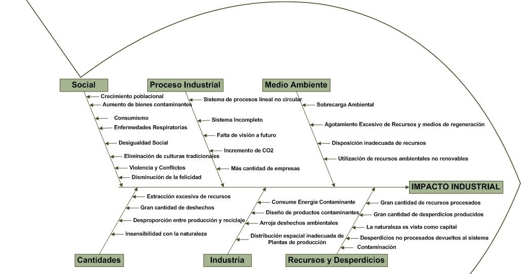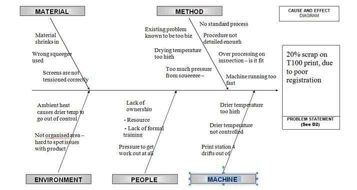

The 6M Method encourages the capturing and assorting of challenging issues under the 6M categories. Also known as Fishbone Diagram (due to its appearance) or Ishikawa Diagram (named after its developer), the mnemonic representation of the characteristic dimensions to contemplate when brainstorming is indisputably significant during problem-solving sessions. The 6M Method in Ishikawa Diagram centers on a problem and explores its prospective causes to solve it and foster wholesome operations.
ISHIKAWA DIAGRAM FOR MANUFACTURING HOW TO
Part 2: How to Use 6M in Cause and Effect Analysis?

Staying keen about calibration errors and other measurement challenges to avoid inconsistencies becomes important under this parameter.
ISHIKAWA DIAGRAM FOR MANUFACTURING MANUAL
Measurement: Inspection, evaluation, and other physical measures – whether manual or automatic.It makes it easy to take note of the many environmental factors that are manageable under ardent considerations and how to handle those that are not. Weather and other natural events fall into this category. Mother-nature: Considers both controllable and unpredictable environmental influences in the operation processes.Does any of the methods relied on in your processes have too many steps and integral activities that don't add value to the whole system? Method: Production and support processes and their application or contribution to service delivery.This parameter checks on the correct specification of materials, their proper storage, labeling, and subsequent usage. Material: Raw materials, components, and consumables management to satisfy production and service delivery.Is the machinery employed for production capable of delivering the intended output? Are machines and tools well-managed to achieve excellence?

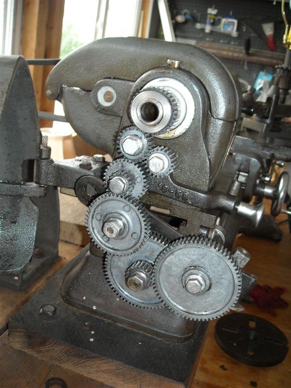
Machinery: Touches on machines, tools, and other facilities together with their underlying support systems.Whether the staff has quality consciousness, sense of responsibility and discipline are answered by this 6M method aspect.

This parameter checks on whether the personnel's technical proficiency and experience are up to standard.


 0 kommentar(er)
